

- Product Introduction
Introduction:
The tester is designed according to the BS476-12:1991. Method of test for ignitability of products by direct flame impingement.The accuracy of the tester meets the requirements of relevant standards and meets the control requirements for the accuracy of measurement.
Model :FTech-BS 476-12

Standards:BS 476-12
Structure:
1.Voltage:220V + 10%, 50Hz;
2.Burner.
(1)Ignition source D. A gas burner comprising a 185 mm long horizontal stainless steel tube(12.0 mm outside diameter, 9.0 mm inside diameter) closed at each end and fitted with a central gas supply pipe. The burner tube shall have a row of 14 holes of 1.5 mm diameter at 12.5 mm centres arranged so that the gas jets issue at an angle of 45 below the horizontal .
The flowmeter shall be calibrated to supply a propane gas flow rate at 25C of 2 l/min
NOTE Under these conditions the flame height is approximately 240 mm.
(2)Ignition source E. a gas burner comprising a 185 mm long horizontal stainless steel tube(12.0 mm outside diameter, 9.0 mm inside diameter)closed at each end and fitted with a central gas supply pipe. The burner tube shall have a row of 14 holes of 1. 5 mm diameter at 12.5 mm centres arranged so that the gas jets issue at an angle of 45 below the horizontal.
3.A burner carriage consisting of a movable column which incorporates a 10 mm On x 1 mm wall stainless steel tube terminated by a threaded boss to which the various burners can be fixed.
4.A length of 5 mm internal diameter hose not greater than 3.0 m in length to connect the flowmeters to the burner carriage via a gas cock mounted on the carriage.
5.Test frame. A horizontal steel platform to which a sliding burner carriage and burner tube are attached. At one end of the platform, means shall be provided to maintain the specimen holder in a vertical position.
6.Specimen holder. The vertical specimen holder shall be capable of accommodating the largest size of specimen Specimens shall be gripped at intervals along both vertical edges.
For narrower specimens, holders may be designed to fit within the widest holder in order to provide a common position for testing.
7.Burner carriage and tube. The ignition source shall be mounted on a burner support tube fitted to the burner carriage(see Figure 1). The tube shall be equipped with means to allow vertical adjustment of the ignition source position as required by the various tests. The burner carriage shall be designed in such a way that the distance between the burner and the specimen is obtained accurately. reproducibly and automatically and manufactured so that the ignition source can be brought into the prescribed position smoothly and within 1s.
8.A clamp used to fix the soft wood。
9. Draught shields. Draught shields of 9 mm thick non-combustible board, triangular in shape, with a base of approximately 500 mm and approximately 750 mm in height shall be provided for use with ignition sources A. B and C.
Parameters
1.Propane flow:10-1000±5 mL / min,
2.Air flow:0-100L/min
3.Burning angle:45 and 90º;
4.Various test parameters can be set directly on touch screen.。
5.Control: touch screen +PLC control
6.Test time: 1-99mins arbitrary set.
Gas and air system
1.Gas (customer prepared)
(1)Propane and LPG。
(2)Air supply pipe, compression release valve, safety valve.
2.Air source system (customer prepared)
(1)Compressed air: 0-6kgf
(2)Switch valve and pressure gauge
-
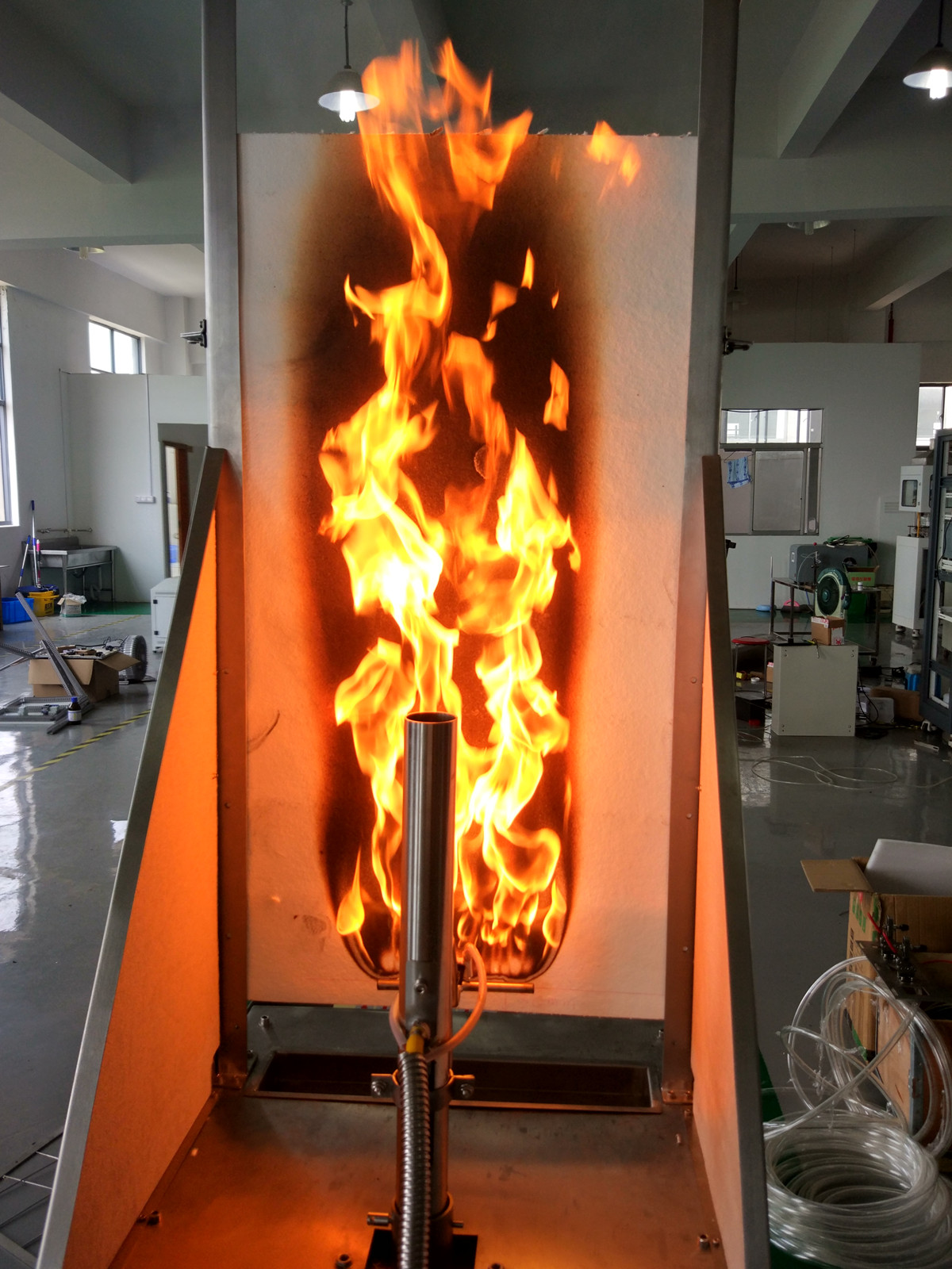 Direcct flame impingement Tester with BS 476-12 FTech-BS 476-12
 -
 En ISO 11925-2 Single-Flame Source Tester FTech-ISO11925-2
 -
 Building Material Noxious Gas Analysis Apparatus with DIN53436 FTech-DIN53436
 -
 Foam Plastic Horizontal Burning Test Machine with ISO 9772 FTech- ISO 9772
 -
 Photovoltaic Flammability Test Apparatus,ISO 11925-2:2010,IEC61730-2 FTech-IEC61730-2F
 -
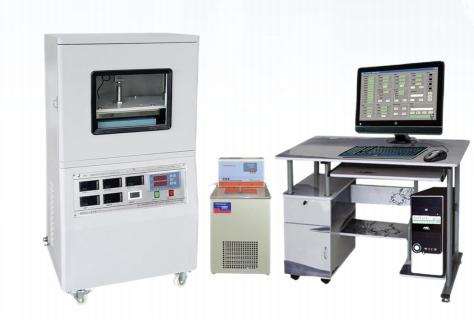
 Thermal Conductivity Meter with ISO 22007 FTech-ISO 22007
 -
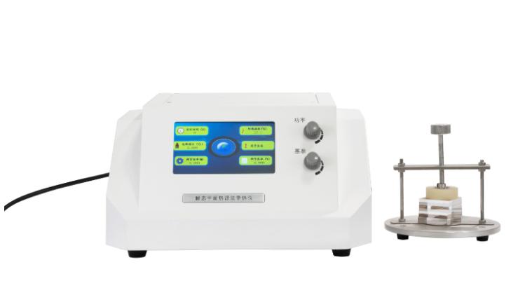
 High-precision Material Thermal Conductivity Tester (Flat Plate Thermometer Method) with ASTM E 1530 FTech- ASTM E 1530
 -
 High-precision Material Thermal Conductivity Tester (Flat Plate Thermometer Method) FTech- ASTM E 1530